
 EN
 ZH
 JA


LED Strip Troubleshooting: Fix the 8 Most Common Failures
In projects from architectural accent lighting to home décor and commercial fit-outs, LED strips win on flexible install and soft light—but uneven brightness, dead sections, and yellowing coatings turn into rework headaches fast. Most failures trace back to the power supply, materials, or install method. This LED strip troubleshooting guide breaks down eight of the most frequent faults—with the symptoms, root causes, and fix steps for each—so you can resolve issues quickly and choose strips that avoid them in the first place.
I. Eliminating the “Bright Start, Dim End” Issue in LED Strips: Checking Voltage Drop and PCB Material/Thickness
1. Symptom: The LED strip is bright at the power connection point but becomes noticeably dimmer at the far end; this phenomenon is known as voltage drop.
2. Solution: First, verify if a 24V power supply is being used. Since 12V strips carry lower current, they are prone to voltage drop when a single continuous run exceeds 5 meters. If a single run reaches 10 meters, powering the strip from both ends is strongly recommended. Additionally, beyond voltage considerations, check whether the strip’s PCB (Printed Circuit Board) meets the 2oz (70μm) standard (for instance, Mingxue Optoelectronics uses 2oz–3oz rolled-copper PCBs to minimize voltage drop at the source). Thinner boards, such as 1oz (35μm) versions, have higher internal resistance, which exacerbates voltage drop.
II. Addressing Partial LED Strip Failures (Dead Sections): Examining Soldering and PCB Quality
1. Symptom: A section of an LED strip fails to light up during operation; the individual LED beads may flicker or light up intermittently when pressed.
2. Diagnosis: This is typically caused by a “cold solder joint” (poor connection) or a broken circuit trace on the PCB.
3. Solution: Choose manufacturers that utilize fully automated SMT (Surface Mount Technology) assembly processes. Ensure that all soldered connections—including wire-to-strip joints—are clean and free of accidental bridges (solder splashes connecting adjacent points). High-quality solder joints should appear smooth, rounded, and silver-bright. When sourcing, avoid “die-cut” (stamped) PCBs in favor of electroplated PCBs; the copper layer on die-cut boards is held in place by adhesive, making it highly prone to short-circuiting or peeling off, whereas the copper layer on electroplated boards is bonded to the substrate with superior strength.
III. Troubleshooting LED Strips That Fail to Light Up After Cutting: Verifying Proper Cut Placement
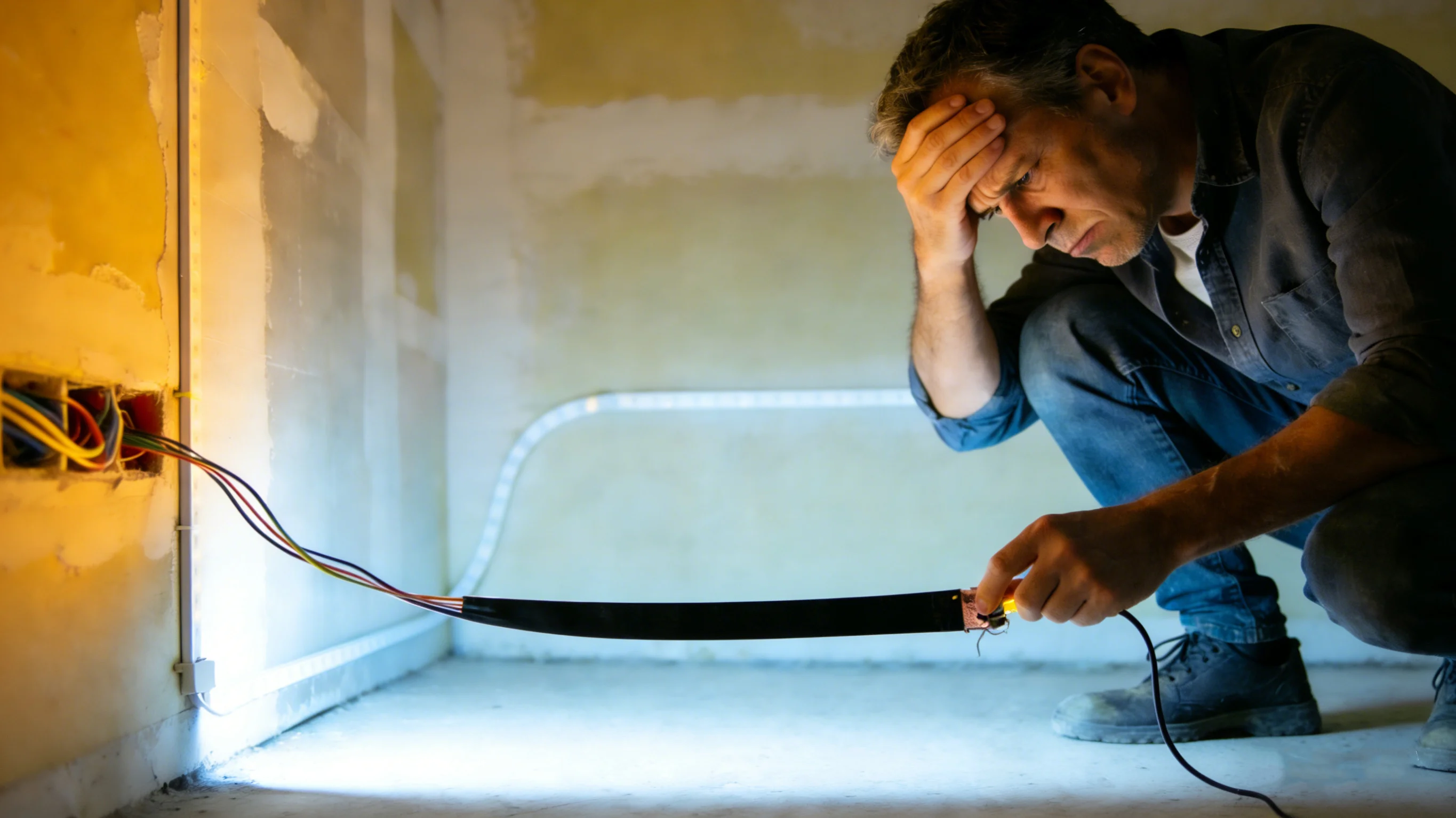
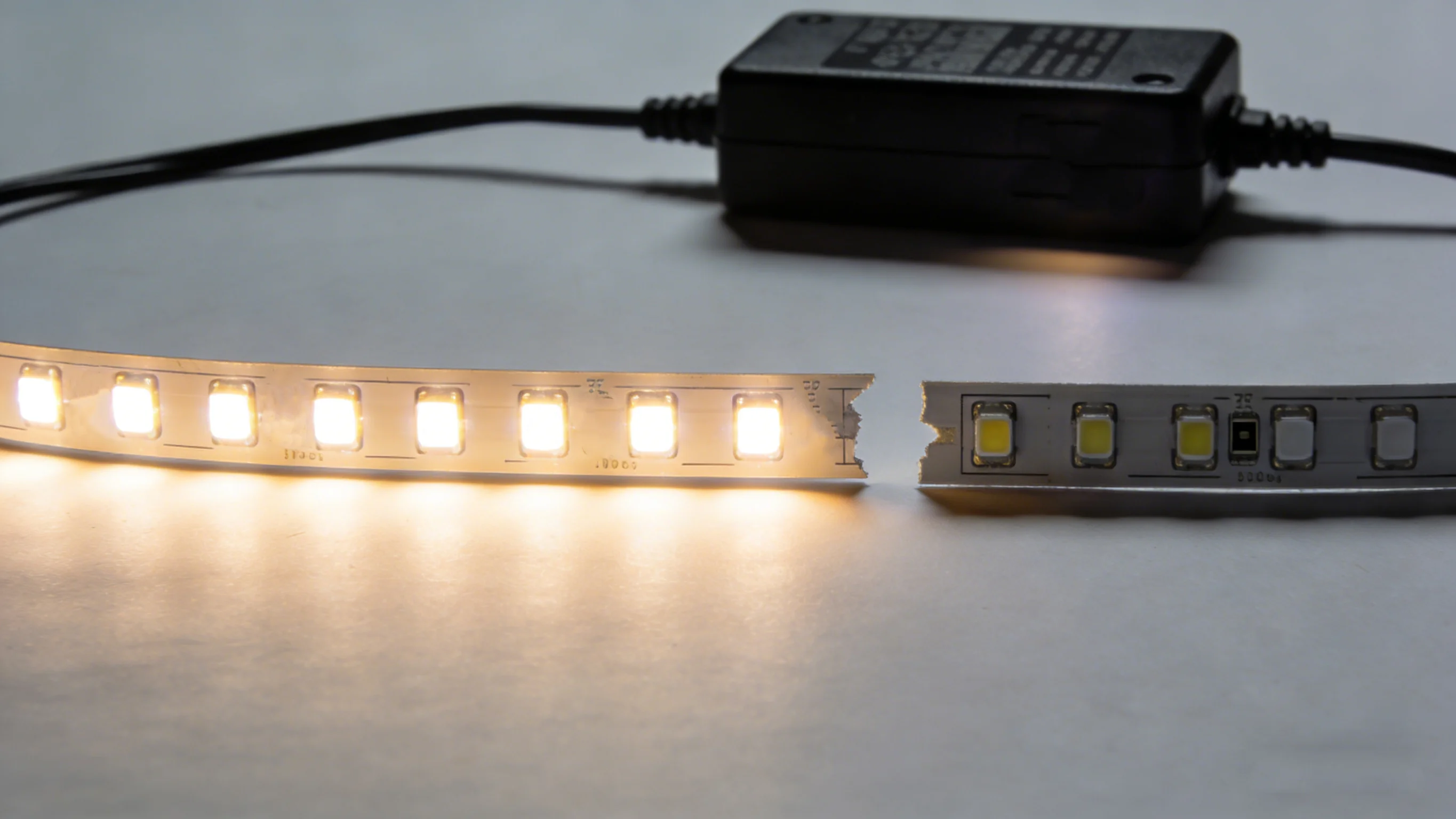
1. Symptom: A section of the LED strip fails to illuminate after being cut.
2. Solution: Carefully inspect the cut site. If the strip was cut improperly, the internal circuitry may have been damaged, preventing the current from flowing through that section. You must remove the damaged segment and reconnect the strip, ensuring that the connection points align precisely with the designated markings on the PCB. Additionally, check to see if any LED beads were accidentally damaged during the cutting process, as this would also cause the section to fail.
IV. Troubleshooting “Dual-CCT LED Strip Malfunction”: Checking for Incorrect Wiring Sequence
1. Symptom: After connecting the dual-CCT (Correlated Color Temperature) LED strip, only one color illuminates, or the controller emits smoke and burns out when adjusting the cool/warm color temperature.
2. Solution: This is a classic case of incorrect wiring sequence. Dual-CCT LED strips typically utilize a “Common Anode” design, featuring one positive terminal corresponding to two negative terminals (yellow and white wires). Reversing the positive and negative connections, or connecting the two negative terminals in parallel to the positive output, will directly cause the controller to overload and burn out. Therefore, before installation, carefully check the wiring sequence markings (“+” and “CW/WW”) on the LED strip’s PCB and ensure they align correctly with the controller’s terminals to prevent damage to the controller.
V. Addressing “Yellowing/Brightness Drop” in Waterproof LED Strips: Investigating Material Aging and Yellowing of the Encapsulant
1. Symptom: After 3–6 months of operation, waterproof LED strips that were originally pure white become noticeably yellowed. Furthermore, the overall brightness of the strips decreases significantly as a result of this yellowing.
2. Solution: This issue is caused by the chemical yellowing of the waterproof encapsulant (such as low-quality PU or epoxy resin) due to the combined effects of ultraviolet (UV) radiation from the sun and heat generated by the LED chips. Yellowing not only alters the color temperature but also absorbs a substantial amount of light, leading to significant light degradation. Currently, durable outdoor-rated waterproof LED strips typically use silicone, as it possesses superior resistance to yellowing. However, the quality of silicone can vary; for instance, there is a distinction between fumed silicone rubber and precipitated silicone rubber.
3. Why is precipitated silicone prone to yellowing, while fumed silicone is not?
3.1. Fumed Silicone Rubber: Produced via the fumed (vapor-phase) process, this type of silicone features exceptionally high purity.
3.1.1. High Purity: It is synthesized through the high-temperature hydrolysis of silicon tetrachloride in a hydrogen-oxygen flame, resulting in a material almost entirely free of impurities and metal ions.
3.1.2. Structural Stability: Fumed silica has fewer surface hydroxyl groups, which contributes to its high chemical stability.
3.1.3. High Transparency: Fumed silicone can achieve a very high level of transparency. Because its base color is exceptionally clear, even minor changes are difficult to detect.
3.2. Precipitated Silicone Rubber: Produced via a chemical precipitation process involving acids or bases, this type of silicone inevitably retains certain impurities.
3.2.1. Residual Impurities: The production process can leave behind impurities such as sodium salts and metal ions. When subjected to high-temperature vulcanization or long-term exposure to UV radiation, these impurities undergo oxidation, causing the material to shift from transparent/white to a pale yellow color. 3.2.2. Influence of pH: It is often difficult to fully neutralize precipitated silica to a neutral pH. An acidic environment accelerates the degradation of chemical bonds within the silica, leading to the formation of yellow-colored byproducts.
3.2.3. Transparency and Base Color: Precipitated silica inherently possesses lower transparency than fumed silica (appearing slightly milky-white); consequently, even a minor degree of yellowing becomes highly noticeable visually.
| Characteristics | Precipitated Silicone | Fumed Silicone |
|---|---|---|
| Yellowing Resistance | Poor (Susceptible to impurities & high temperature) | Excellent (Ultra-pure, maintains long-term transparency) |
| Transparency | Translucent or milky white | Highly transparent (Crystal clear) |
| Tensile Strength | Moderate | Very high (Better elasticity & toughness) |
| Cost | Low (Suitable for low-end industrial parts) | High (Suitable for medical, food & high-end electronics) |
| Typical Applications | Sealing rings, keypads, general miscellaneous parts | Phone housings, drinking straws, medical catheters, high-end lighting |
4. Practical Advice: When selecting products for lighting projects, it is essential to verify the material of the neon strip’s encapsulation. For high-end projects, specify strips manufactured using the fumed silicone extrusion process. Our waterproof strips utilize this fumed silicone extrusion method, effectively preventing yellowing for six months or longer.
VI. Addressing Abnormal Noise: Selecting High-Quality Power Supplies and Ensuring Power Redundancy
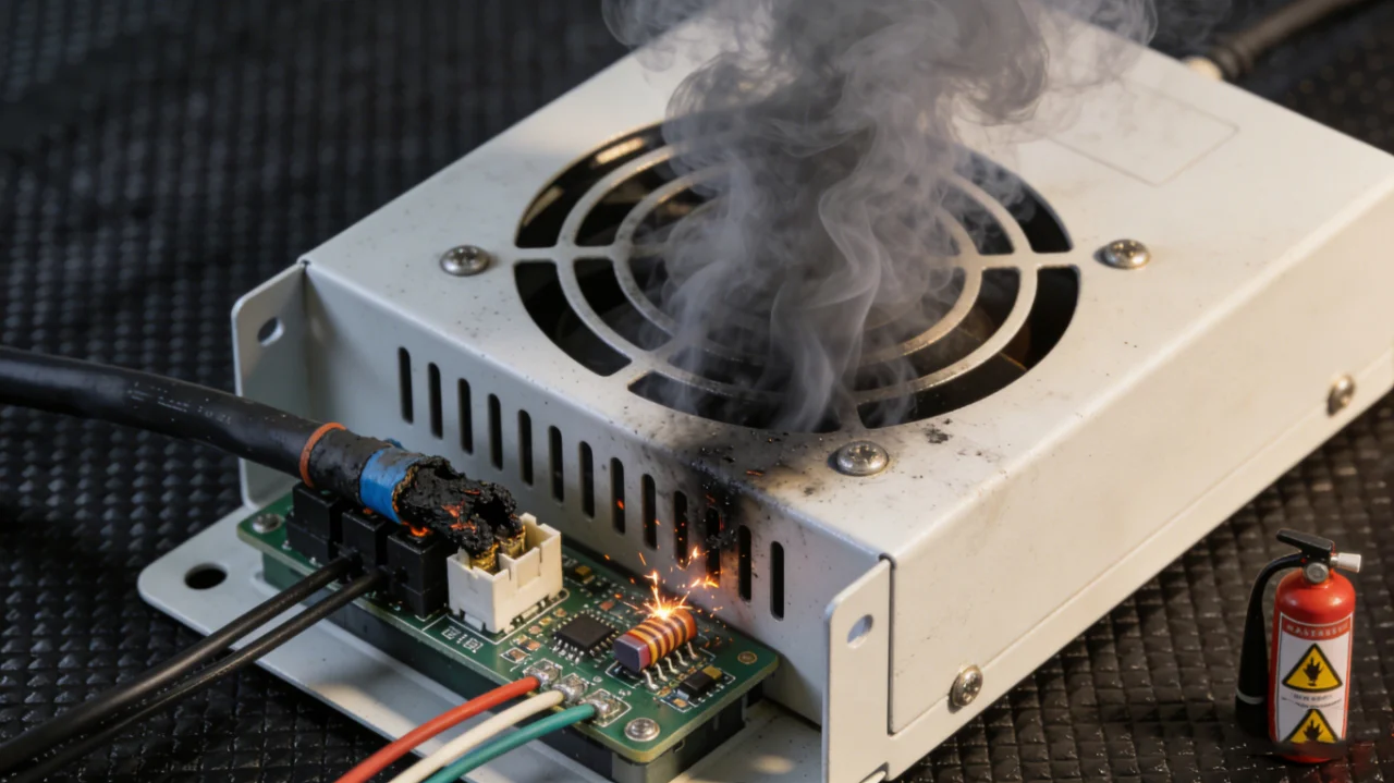
1. Symptoms: The power supply emits a buzzing or abnormal sound; in severe cases, black smoke may even emerge from the unit.
2. Troubleshooting Advice: Calculate the total power requirement of the LED strips and compare it with the power supply’s rated capacity to determine if the system is operating near full load or significantly overloaded for extended periods.
3. Solution: If the power demand of the LED strips exceeds the power supply’s capacity, the unit is at risk of failure and could potentially cause a fire. During installation, power supply configuration must strictly adhere to the power redundancy formula: Total Power = Strip Power × Length × 1.25 (safety margin). Additionally, the power supply must be located near an access panel to facilitate future maintenance.
VII. Preventing damage during LED strip installation: Use tools properly and avoid forceful installation methods.
1. **Symptoms:** After installation, the LED strip fails to light up in certain sections, or the LED beads are found to be damaged.
2. **Troubleshooting:** Installers may—in an effort to save time—use hard tools to press the strip firmly into the mounting channel (especially aluminum channels), inadvertently damaging the internal PCB circuitry.
3. **Solution:** Exercise great care when working with these channels and use appropriate tools; for instance, the tool shown in the image is specifically designed for installing strips into aluminum channels. Additionally, during transport and unpacking, avoid stepping on the flexible LED strips or subjecting them to 360-degree twisting, as such actions frequently cause the strips to fail.
VIII. Permanently Resolving “Intermittent Flickering” in LED Strips: Troubleshooting Water Ingress, Oxidation, and Loose Connections
1. Symptom: The light strip begins to flicker after exposure to moisture or a period of operation; the fault often occurs at the circuit board connection points.
2. Solution: Inspect solder joints for moisture-induced oxidation or poor contact. In lighting projects, if solder pads lack anti-oxidation treatment (such as the ENIG/immersion gold process), a high-impedance oxide layer easily forms in humid environments, impeding normal current flow. Re-soldering and applying a waterproof seal are necessary to ensure a secure, reliable connection.
The stable operation of flexible LED strips relies on comprehensive quality control—from material selection and installation standards to ongoing maintenance. Features such as 2oz thickened PCBs (mitigating voltage drop risks), vapor-phase silicone (resisting outdoor yellowing), ENIG processing (preventing joint oxidation), and 1.25x power redundancy (ensuring electrical safety) are not only key to troubleshooting but also the foundation of a high-quality product.
With competition in the 2026 lighting market intensifying, choosing a reliable light strip helps lighting projects avoid the risks of rework and reduce overall costs. Mingxue Optoelectronics has specialized in mid-to-high-end lighting solutions for 20 years. Backed by a 24,000-square-meter modern facility and a 20-person R&D team focused on core technologies, the company insists on using premium materials—such as 2oz–3oz rolled-copper PCBs and high-grade vapor-phase silicone. Through fully automated SMT assembly and an 8D quality traceability system, every meter of light strip meets UL, CE, and SAA certifications as well as new ERP energy efficiency standards, effectively eliminating common issues like “bright head/dim tail” effects, yellowing/lumen depreciation, and localized LED failure at the source.
Whether for the refined requirements of home renovation or the rigorous standards of large-scale lighting projects, Mingxue Optoelectronics offers the ideal LED strip solution. A professional technical team provides end-to-end support, offering one-on-one guidance from product selection to troubleshooting, ensuring your project saves time, money, and effort.
Published by Mingxue Lighting | Founded 2005 | Shenzhen R&D Center + Foshan Manufacturing Base | 24,000 sqm | ISO 9001 Certified


